


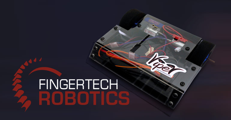
Viper kits make building your first robot fun and easy. It’s a great way to get into the sport without a huge investment and find out what type of robot you really love to drive. They are wonderful for beginners, and people who need a platform to build upon!
1. Solder esc to drive motor
The esc (motor speed controller) controls how fast and in what direction the motor spins. I really recommend a process called “tinning” in which you heat up the connectors and place a tiny bit of solder on them prior to attaching the wire to it. I normally “tin” the connectors of esc, and the wires of the motor, and then solder them together after that. The motors connectors are very delicate, so it’s important to not put too much pressure on the motor connection tabs when heating them. After you tin the wire and the connector, heat up the motor connector to the point that the solder appears glossy and put the wire in the pool of solder, adding extra if needed. Make sure the red wire goes to positive, and the black wire goes to negative. Gently tug on the wire to make sure you have a good connection on both wires when it’s finished!
2. Mount motors to frame
The viper kit motors come with amazing face mounting screw holes built into the side of the robot, and are very easy to line up. Rotate the motors until you see the holes for the screws to go through, and then screw them in with the appropriate sized screws.
3. Wire the switch
One side to the positive side of the battery, one side to both of the drive motor speed controllers positive input. Use the tinning method to prep the switch connectors, the positive drive motor esc inputs and the wire. One length of wire will connect to the battery female plug, and one of the switch connectors. The other switch connector will use two wires connected to transfer power to the positive input on both motor speed controllers.
4. Wire the negative side of the ESCS
Using the tinning method, prep the negative sides of the motor speed controllers, two wires and the negative side of the battery connector female plug. After you tin, heat up the motor speed controller connector to the point that the solder appears glossy and put the wire in the pool of solder, adding extra if needed, and repeat on the other speed controller.
5. Plug components into Reciever and Bind!
When plugging in any item to a receiver, make sure any power source is disconnected, or at the very least the power switch is set to the off position. Receivers are very easy to damage with “shorts”. Make sure the signal wire, usually white, is plugged into the signal plug, usually marked with a little S on the side. Follow the binding instructions on your controller.
Additional instructions For lifter kit
- Mount Servo to frame
- Plug servo into receiver
- Connect lifter Arm to Servo
- Mount Lifter Arm
Additional instructions for spinner kit
- Wire esc to weapon motor
- Mount weapon motor
- Wire weapon esc to receiver
- Mount weapon
- Bind Receiver to Controller
